Senior Capstone: NASA Dynamometer Adaptation to the Human Shoulder
Fall 2022 - Spring 2023
Our project was award "Best Overall Design" and "Best Prototype" by faculty and industry judges
My team collaborated with the NASA PSION lab to adapt a previously designed knee dynamometer actuator device for use with the shoulder muscle to collect data on astronaut shoulder muscle degradation during spaceflight missions.
Skills: Technical writing, oral communication, rapid prototyping, machining, woodwork, SOLIDWORKS, MATLAB, ANSYS, mathematical analysis, teamwork, collaboration with industry sponsors.
My Role:
I initiated the relationship with NASA by taking a leap of faith and contacting various NASA engineers on linkedin to share my goal of contributing to a NASA biomedical project for my senior capstone. I was directed to the PSION lab in Houston who found a project that they requested my capstone team to take over. I then worked with my Villanova faculty advisor to formulate a clear project overview and timeline.
Within the team I preformed the roles of CAD lead, calculations and FEA lead for the mounting bolts and shaft components, as well as rapid prototyping and machining lead.
As the CAD modeling lead, I had the opportunity to collaborate with NASA engineers to manipulate their preexisting SOLIDWORKS models and design specialized components to allow for seamless interface between their actuator and our rotational device. I practiced GD&T standards while developing engineering drawers for our university machinist, developed skills in shell modeling, and created a dynamics SOLIDWORKS assembly to demonstrate the functionality of our device.
During the POC stage, I contributed to the solid mechanics and safety evaluation of our device by preforming shear, strain, and deformation calculations for the mounting bolts and main shaft components of our design. These two components were expected to experience the highest stresses, so I also performed FEA analysis in Ansys to further support out hand calculations and developed a stronger understanding of system loads.
I was appointed as the rapid prototyping lead for the project due to my experience as a 3D printing makerspace technician at Villanova. I created a full scale model of the actuator and exoskeleton components of the device using FDM printers with PLA material. I worked around bed size and material cost constraints to prototype in a productive manner. I worked alongside our university machinist to fabricate the aluminum and wood components of our part.
Executive Summary:
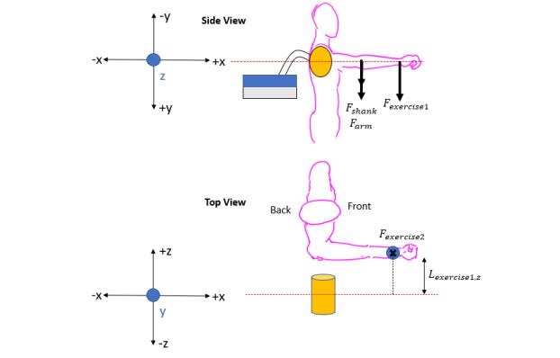
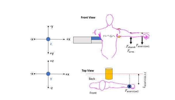
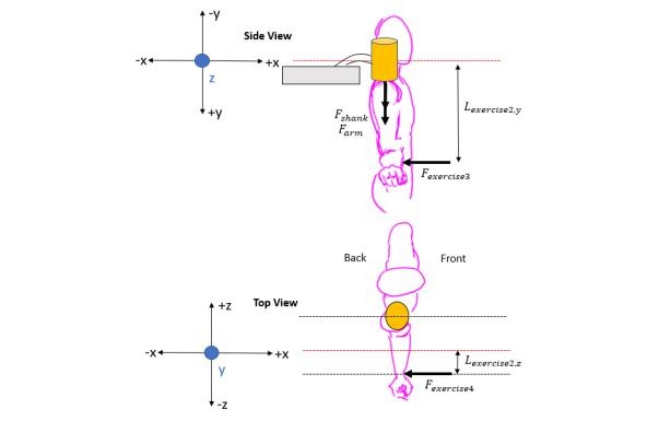
In the hopes of collaborating with the PSION wearable robotics lab at the NASA Houston Space Center for my ME Senior Design Project I reached out to the lab team to formulate this project. The purpose of this project is to design and build an isokinetic shoulder dynamometer, adapted from a previously designed knee dynamometer. This design accommodates the range of 5th percentile women to 95th percentile men, with all load calculations using the worst-case scenario of a 95th percentile male user. The importance of this project lies in its ability to reduce unexpected shoulder injuries and ensure astronaut safety. This project is significant as it aims to create a device that measures astronaut shoulder forces, the results of which can be used to anticipate the onset of shoulder injuries.
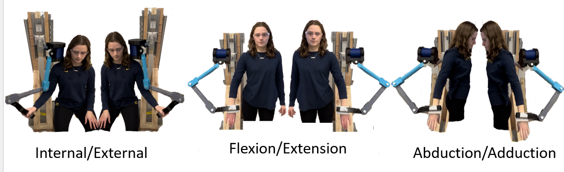
The device must safely and accurately measure the internal torque at the shoulder joint in three
desired motions: flexion/extension, abduction/adduction, and internal/external rotation. It must also be able to transmit the desired maximum torque of 326 Nm and withstand joint velocities up to 400°/second.
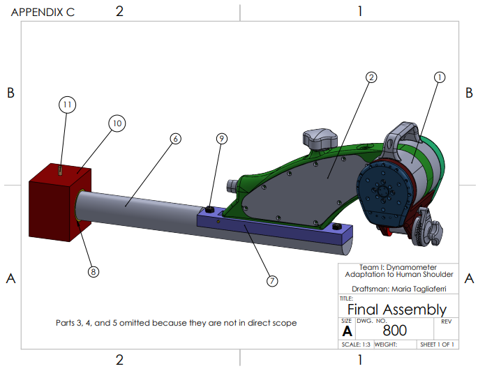
The original design made use of a mounted bearing and shaft to successfully achieve dynamometry in all desired planes of motion. Since the detail design was proposed, two major design changes were made. The wall attachment block, which is a piece that houses the bearing and shaft assembly, was determined to be excessive in size. Therefore, the size was reduced. Additionally, the effect of twisting moments was omitted from the previous shaft failure analysis. The mounted bearing was switched out for a sleeve bearing in order to minimize the twisting moments.
The assembly process was facilitated by the testing and commissioning plan, which was a checklist used to verify device functionality according to design specifications. All five sections of the testing and commissioning plan were followed, ensuring a safe and accurate assembly of the device. A few minor issues arose during the prototyping of the device. The positioning pin was difficult to insert through the wall attachment block, bearing, and shaft assembly. Various machining techniques were performed to decrease diameter and remove other sources of friction, ultimately allowing for easier insertion. Additionally, the Villanova University machine shop lacked the appropriate bolt tap for the size of bolt purchased. The bolts were switched out to match the available bolt tap. Once the troubleshooting of issues was complete, the testing process commenced. Testing measures proved overall device success.
The final design leveraged both user and device movement to create an elegant solution to a
complex problem. To transition from flexion/extension to adduction/abduction, the user repositions
their body around the face of the actuator. A shaft, sleeve bearing, and positioning pin are leveraged to rotate the actuator assembly for use in internal/external rotation. The design securely holds the NASA actuator in place, allowing for the accurate measurement of shoulder forces across the various exercises. All performance specifications and design constraints were achieved. The rotation feature of the device ensures that the actuator maintains a range of motion up to 110°, and this was proven through the use tick marks on the device, each representing 10°. A spring-mass oscillator was used to create the maximum torque and generate a frequency that matched the maximum joint velocity. This was proven through video frame measurements to prove displacement and the timing of oscillations to prove the period length. A S-N curve was used to justify the lifetime of the device.
The project was allocated a budget of $370, which includes $34 of contingency. The chosen bearing was out of stock during the time of purchase; therefore, a more expensive bearing was purchased, increasing the actual cost of the bearing. However, the project remained within budget overall by dipping into the contingency and due to the lower actual cost of several components compared to their estimated cost. The total actual cost was $349.
Final Design Report
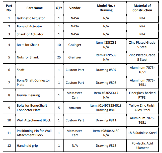
Final Design and BOM